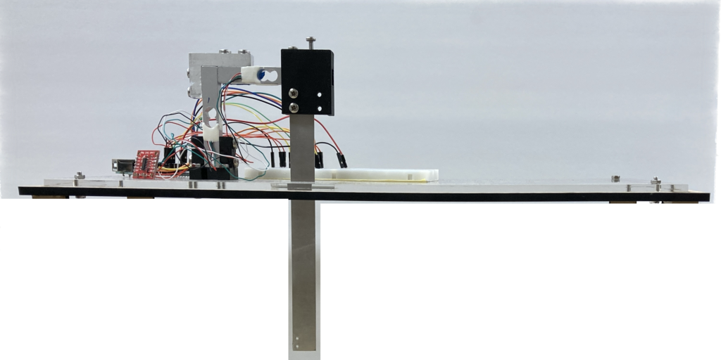
This guide will show you how to fabricate a two-axis force balance that will allow you to measure lift and drag on an object in a wind tunnel, shown below. The force balance is accurate, having a mean absolute percentage error of only 2.5% under static loading conditions for cantilevered loading conditions and 1.1% for symmetric loading conditions. The force balance is currently fitted for an AEROLAB Educational Wind Tunnel, but the base could be redesigned for adaptation to other wind tunnels. To learn more about how the accuracy was determined and for a sample educational lab, please refer to our paper.
Source: Jessica Weakly, Sarah Ho, Erica Feehery, Bruce Kothmann, and Cynthia Sung. “A low-cost, adaptable system for lift and drag measurement in an educational wind tunnel”. In 2024 ASEE Annual Conference and Exposition. 2024.
Fabrication Files
Off-the-shelf Components
- Two Sparkfun 10 kg Load Cells (TAL220)
- Two HX711 Load Cell Amplifiers
- Arduino Uno
- Breadboard
- Wires
- M4 Nuts and Bolts
- M5 Nuts and Bolts
- M5 washers
Laser Cut Files
- Base: Top Plate, Bottom Plate
- Sting
- (optional) Calibration Test Stand Files
3D Print Files
- Base Connector
- Sting Connector
- Bracket or make it on a milling machine using this drawing
Code
- Collect data from the two load cells (Read_2x_load_cell.ino)
- (Optional) Collect data from the load cells while adjusting angle of attack using a motor (Read_2x_load_cell_with_encoder_angles.ino)
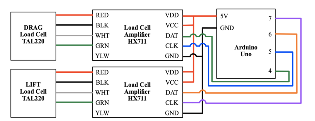
Circuit Diagram
User Guide
Calibrate the Load Cells
- Connect load cells to the amplifiers, taking care to solder the wires from the load cells to the amplifiers.
- Construct the circuit.
- Download the HX711 Library.
- Perform the calibration of each load cell, using the instructions from Sparkfun. Record the calibration factor for each load cell to use in the code.
Assemble the Force Balance
- Fabricate the hardware components on the laser cutter and using 3D printing.
- Attach the top plate and bottom plate to each other using the four corner holes. Check the fit in your wind tunnel before proceeding. If the inner plate is no flush with the surface inside the tunnel, add washers in between the plates.
- Attach the base connector to the base plates using the mounting holes near the middle.
- Take the bare end of one of the load cells and insert it into the sting connector) with the loading direction facing down (towards the sting). This part is press-fit, so take care during this step. BE CAREFUL, because if you overshoot and delaminate the strain gages, the load cell will no longer function correctly. This is now the lift load cell.
- Attach the other end of the lift load cell to the bracket. The load cells have different hole sizes on each side, so you will need to find the end of the bracket that matches. The bracket should be on top of the lift load cell. Take care not to pinch any wires.
- Attach the other load cell to the bracket. It is now the drag load cell.
- Attach the other end of the drag load cell to the base connector, again being careful not to pull or pinch the fragile wires.
- Finally, attach the sting. For storage, you may find it useful to remove the sting when not in use. Otherwise, you can prop it up on some books or make a stand for it.
Collect Data!
- Upload Read_2x_load_cell.ino to the Arduino
- Establish a serial connection to the Arduino at 57600 baud. You can use Arduino’s built in Serial Monitor. This will allow you to copy and paste the data into a text file to save it. You might also consider using an application such as PuTTY.
- Apply a known load and verify that the readings are accurate. If they do not seem accurate, try calibrating the load cells again.
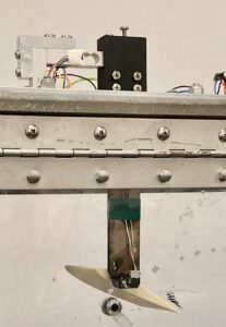
Modification to allow motorized pitch adjustment
If you want to determine the stall angle of an airfoil, it may be useful to a add a motor to enable the pitch angle to be adjusted while a test is running. You will need a few additional components to create the circuit, as well as a modified version of the sting.
Components
Purchase
- Motor: Pololu #2373 1000:1 micro metal gearmotor
- Motor bracket Pololu #989
- Collar for 3mm shaft (not strictly necessary, but a reliable way to attach your prototype): Pololu #1079
- Encoder: Pololu #4760
- Motor driver: DRV8838, Pololu #2990
- 4 AAA or 4 AA batteries (giving a total of 6V)
- Battery holder
Lasercut
- Sting for motor mount: cut this from 1/4″ thick stock
- Support for motor: cut this from 1/8″ thick stock
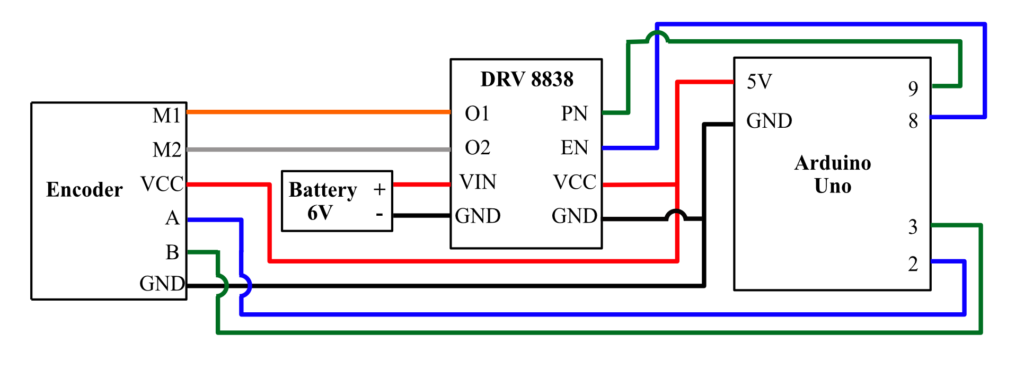
Circuit diagram
The following circuit diagram shows the new connections that you will need to make in addition to the connections already existing for the load cell circuit.
Usage
You can use Read_2X_load_cell_with_encoder_angles.ino to collect data when you have made this modification. This code that will allow you to collect data from the load cell while incrementally changing the pitch angle.
Troubleshooting
- “The code is not working and I am using a Mac”
We have found that Macs tend to have a problem with the HX711 library. We provide a slightly modified version. Replace the following files (generally found in Documents>Arduino> Libraries>HX711_ADC/src) with our versions: HX711_ADC.cpp, HX711_ADC.h, config.h
Funding Support
Support for this project has been provided in part by NSF Grant No. DGE-1845298, by the Pennsylvania Space Grant Consortium, and by the Penn Center for Undergraduate Research and Fellowships.